LMH2 Hypercar Suspension Project
Our group developed the front suspension for a hydrogen-combustion endurance prototype. My main responsibility was the upright, from the first concepts through to the detailed, adjustable design.
Project write-up
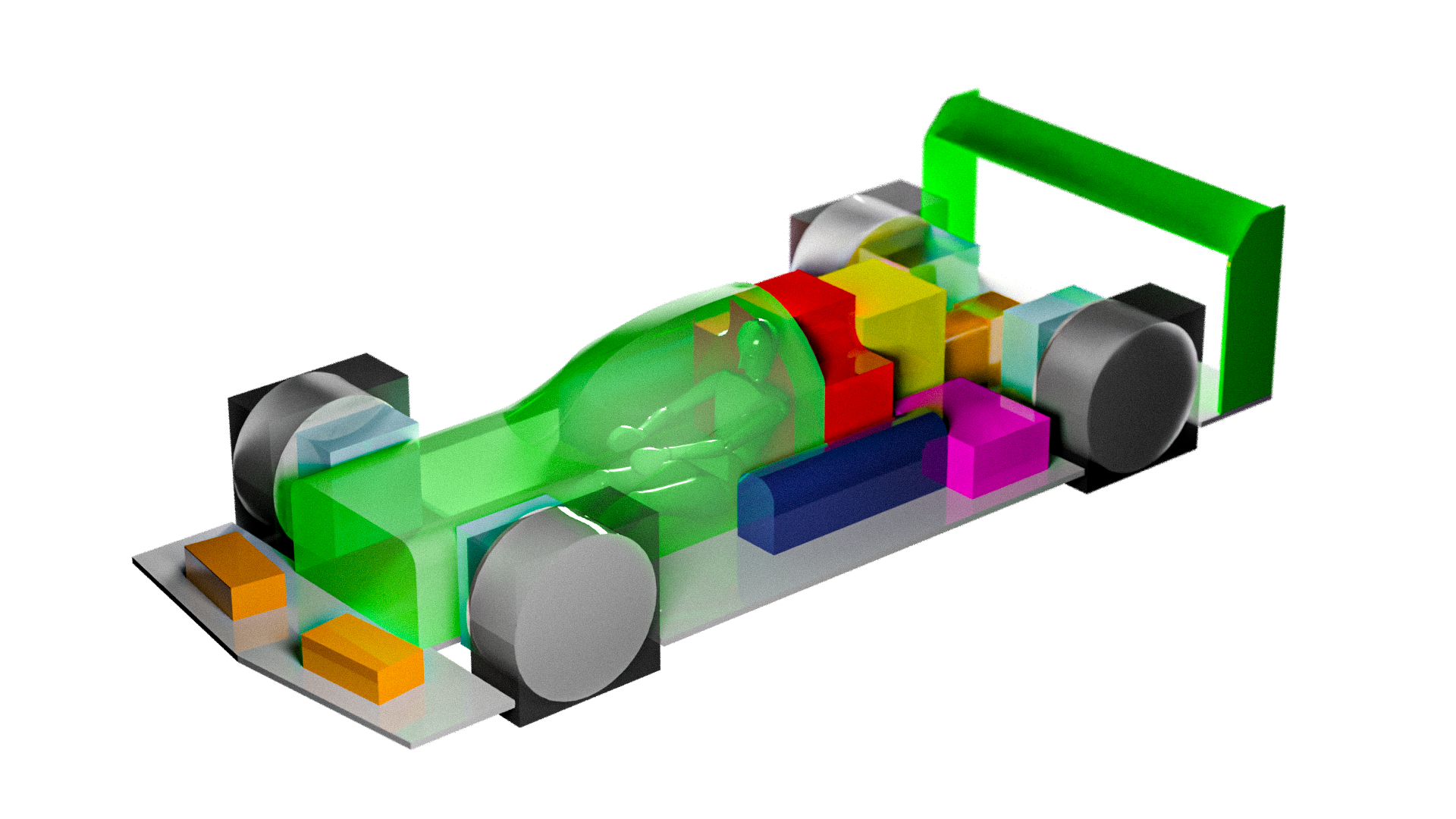
The target of this university project was to create a credible front suspension system for a hypothetical Garage 56-style prototype at Le Mans. This was a university group project, therefore we split the work across vehicle concept, kinematics, chassis, corner assembly, load calculations, FEA, costing and market opportunity. The final concept was based around a hydrogen-combustion WEC Hypercar, using Garage 56 as an opportunity to demonstrate the technology without requiring full homologation from the start.
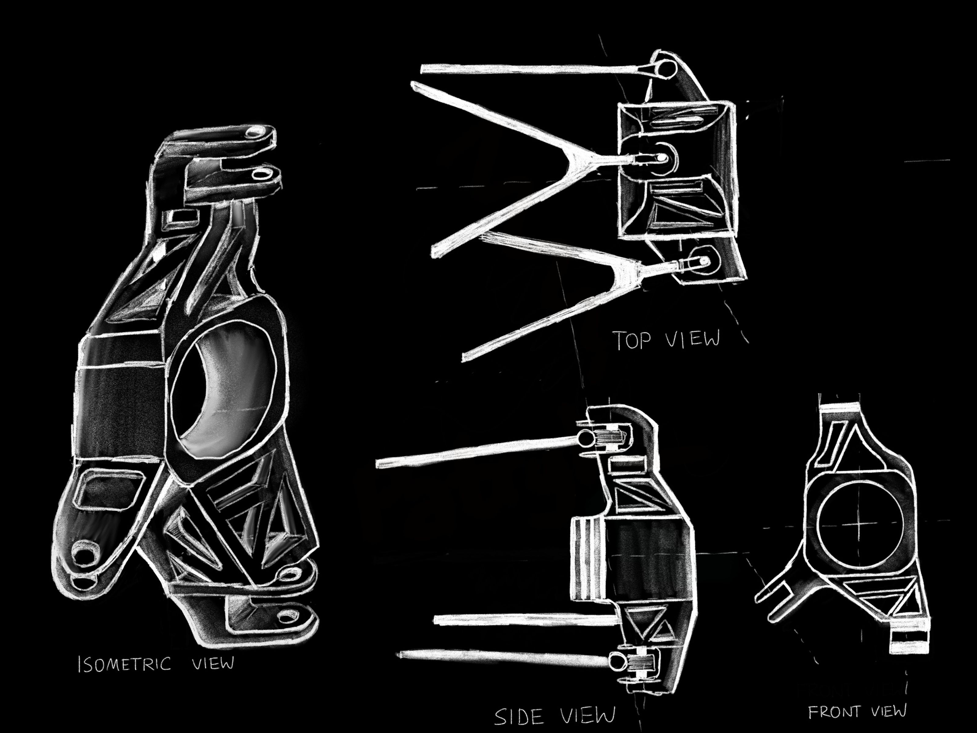
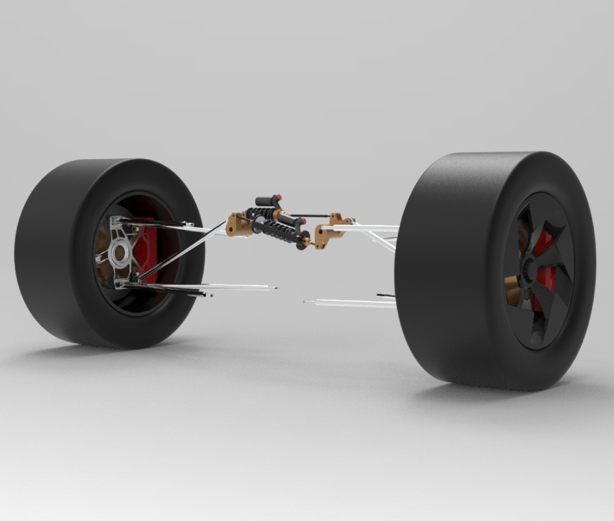
We started by choosing the topic and analysing the market and costing. Having found an opportunity at Le Mans through Garage 56, we each hand-drawn concept sketches of both the vehicle and different suspension layouts. The concepts were compared using decision matrices rather than simply choosing our favourite, with the final vehicle taking inspiration from cars such as the Alpine Alpenglow. For the suspension, we settled on a double-wishbone pushrod layout with a partially decoupled system, allowing independent control of roll and heave while remaining fully passive.
Once the general concept had been selected, the suspension geometry was developed around specific performance targets. The final kinematics achieved only 0.282° of camber change across ±80 mm of bump travel, 0.074° during cornering, less than 0.268 mm of bump steer across ±30 mm, and 25.1% anti-dive. The motion ratio was also designed to be progressive, increasing from 0.06 to 0.42.
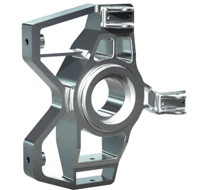
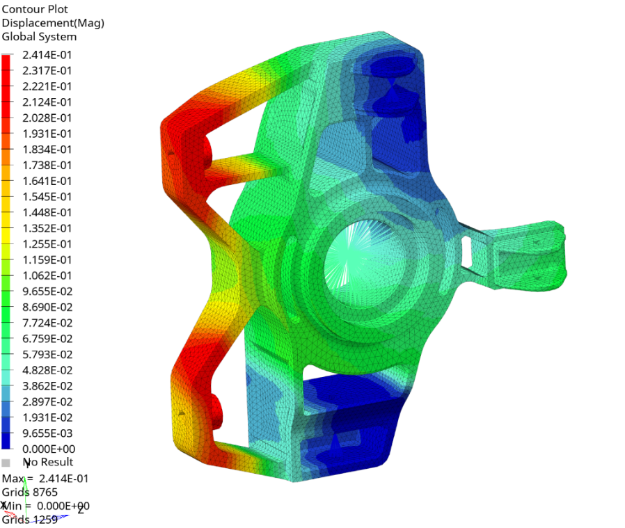
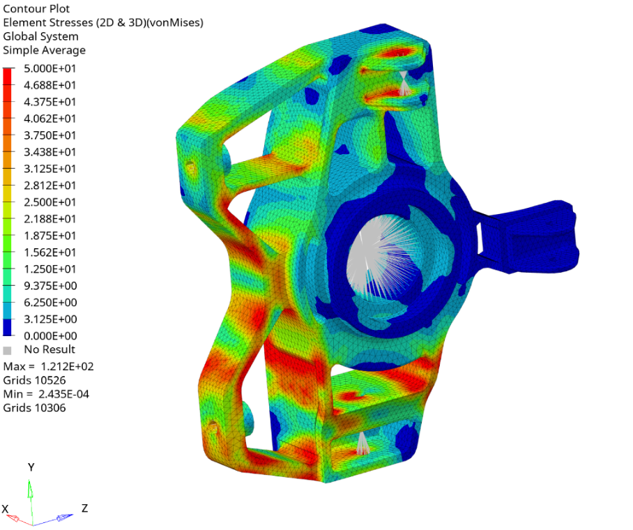
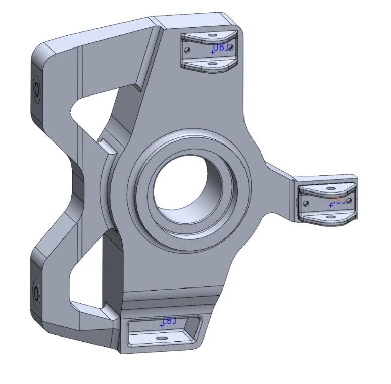
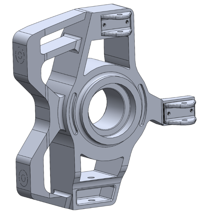
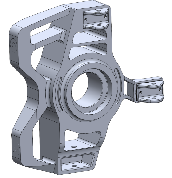
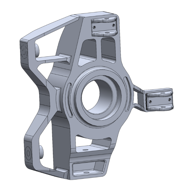
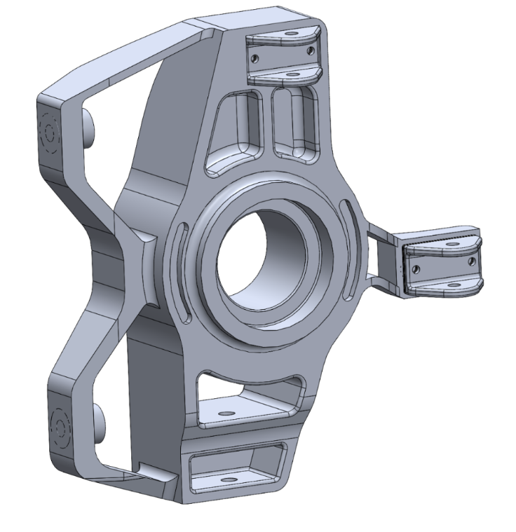
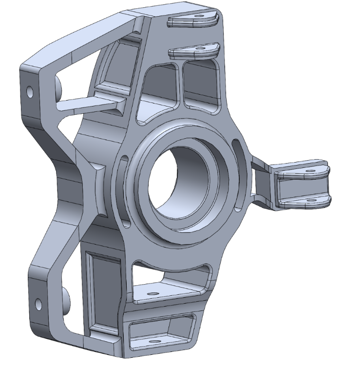
The upright was what we considered the most important element of the corner assembly, and definitely one of the most important parts of the whole project. It connects the wishbones and steering system while also supporting the wheel bearing, brake disc and caliper, so it has to combine stiffness, strength, low mass and manufacturability. Our design target was a factor of safety above 1.5 under both braking and cornering loads, while keeping the component suitable for conventional CNC machining.
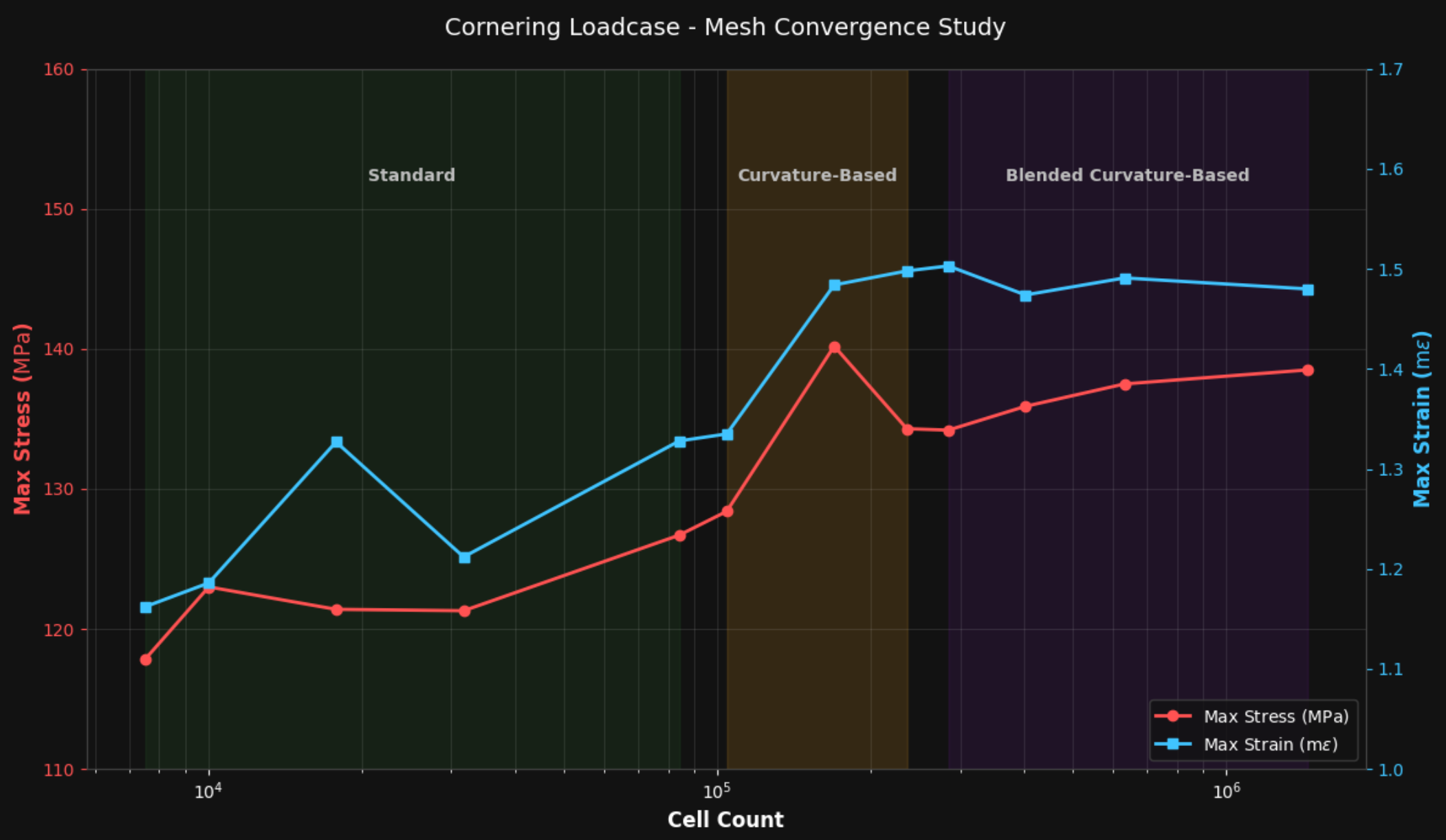
After choosing a main concept from four initial upright ideas, my role in the team was mainly the iterative development of this component, together with its FEA analysis, technical drawings and CAM CNC machining simulation. The upright went through 10 main iterations, with the design changing significantly as material was removed and the load paths became better understood. Across the development, mass was reduced from around 6.0 kg to approximately 3.9 kg, while maintaining suitable structural performance.
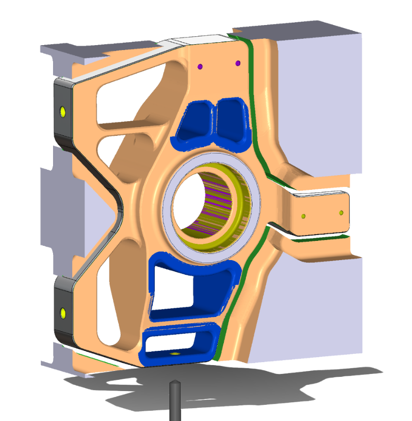
For manufacturing, the final upright was designed around 7075-T6 aluminium and simulated using a 3-axis CNC process. The starting billet measured 105 × 290 × 283 mm and weighed 24.21 kg, with approximately 85.7% of the material removed during machining. Because of the geometry, machining was split into four setups to access the front, rear, wishbone and brake-caliper mounting features.
Overall, the project brought together much more than just CAD modelling. It involved concept development, vehicle packaging, suspension kinematics, structural analysis, manufacturing planning and commercial viability, all tied together into a realistic motorsport engineering workflow. Our final 110-page report, together with the HSMWorks machining simulation, received a 78% final grade (A+).
Design evolution
01 / 06
Model
Interactive model
Drag to rotate. Scroll or pinch to zoom.
Images