Centrifigual Pump Redesign
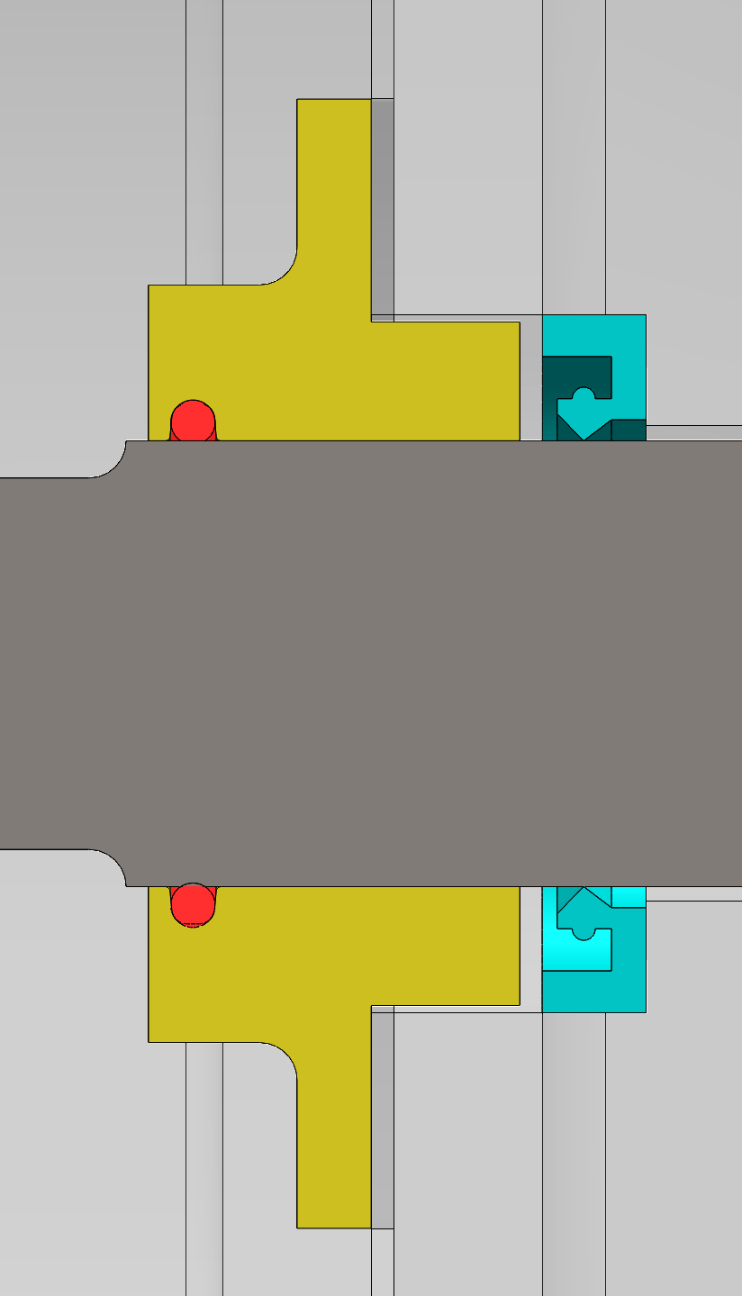
The aim of this project was to model a centrifugal pump from technical drawings and fix some of its fundamental design issues. The main problem was the O-ring groove, which did not leave enough space for the seal to expand properly, causing it to roll, twist and wear faster.
Project write-up
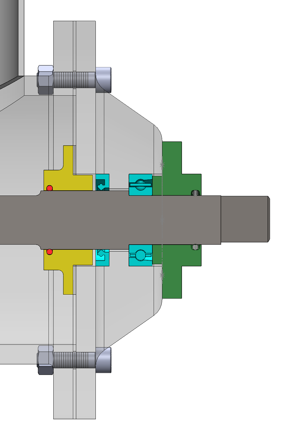
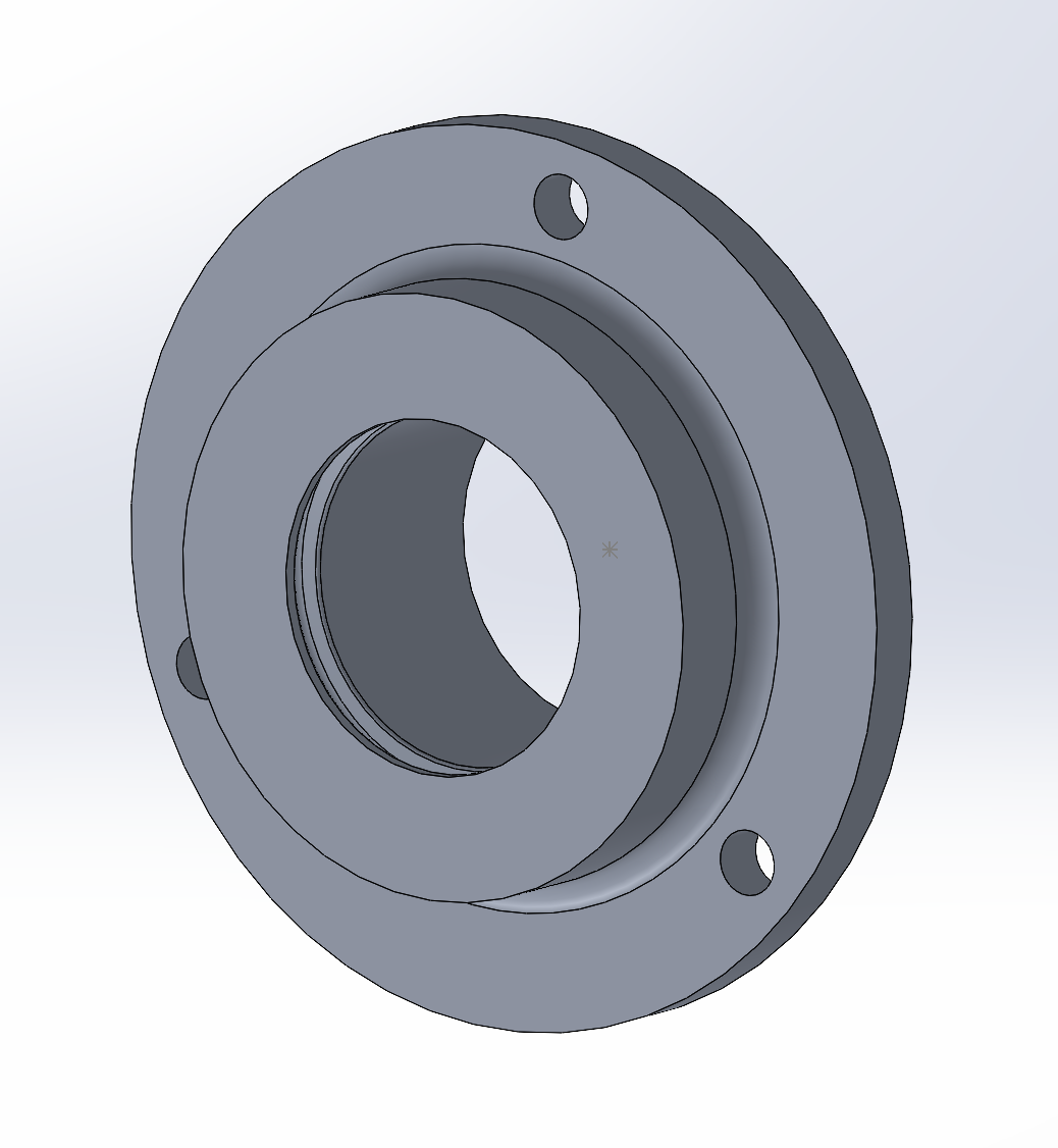
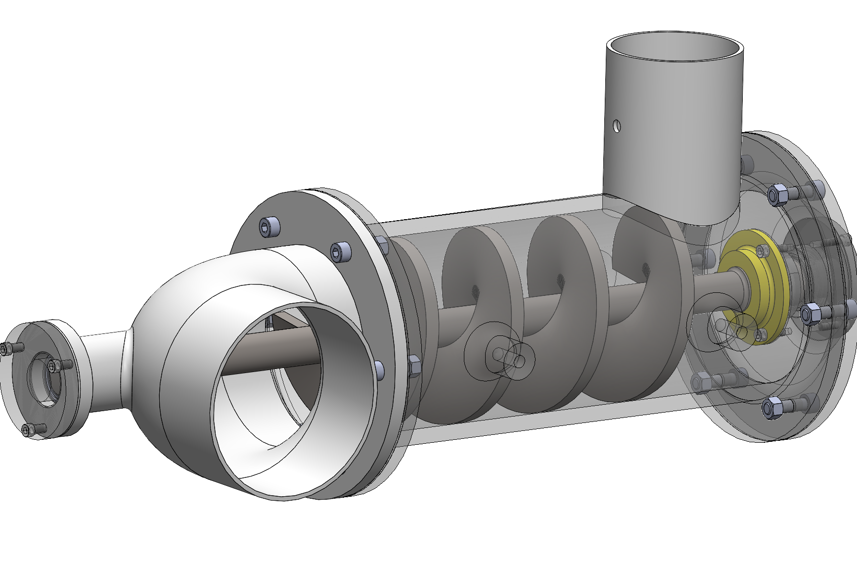
I started by modelling the entire centrifugal pump assembly in SOLIDWORKS using technical drawings provided by Oxford Brookes University. Once the assembly was complete, I focused on redesigning the EndCap 2, which was causing accelerated wear on the O-ring seal.
I first prepared engineering sketches of the original groove and worked out why the geometry was causing the problem. The redesigned groove was based on BS 4518 and included a 5° taper, smaller corner radii and more space for the O-ring to expand. I also calculated the seal squeeze, which came out between approximately 11.7% and 16.7%, and specified a surface roughness of Ra 0.4 μm for the sealing surface.
Another issue was the fit between the EndCap and Endplate, so I changed the central bore to 30 mm and selected an H8/F7 running fit to reduce unwanted movement and vibration. I then produced manufacturing drawings with the required tolerances and GD&T.
After finishing the redesign, I carried out a 3-axis CNC machining simulation. The complete machining process took around 5 minutes 20 seconds in the simulation. I also completed a basic costing and EcoAudit comparison between aluminium 7075-T6 and mild steel. The estimated manufacturing cost of the aluminium EndCap was £63.31.
Overall, it was a useful project for going through the full process of finding a design problem, redesigning the part and then checking how it could actually be manufactured.
Images