OBR26 Side Wing
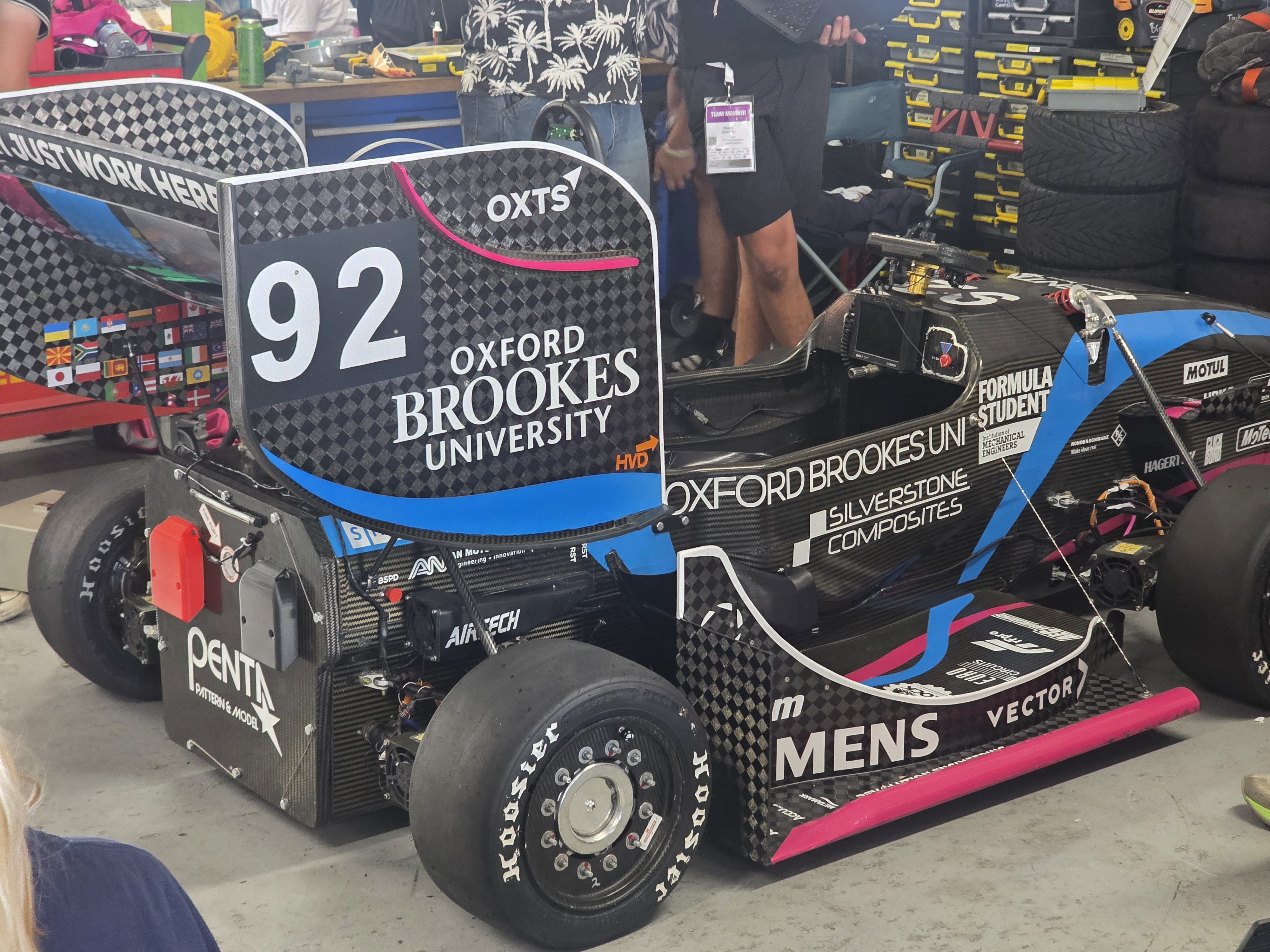
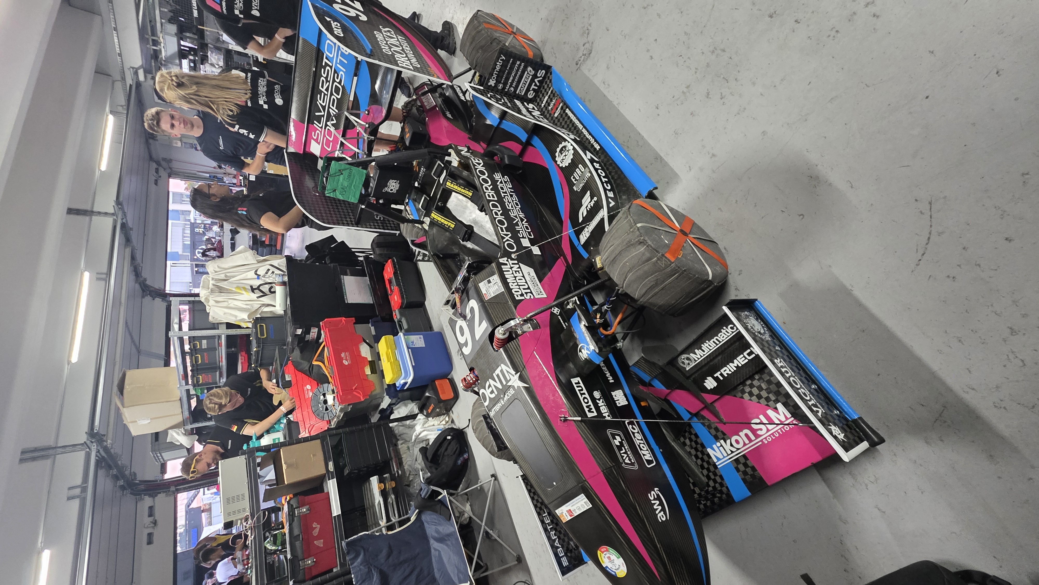
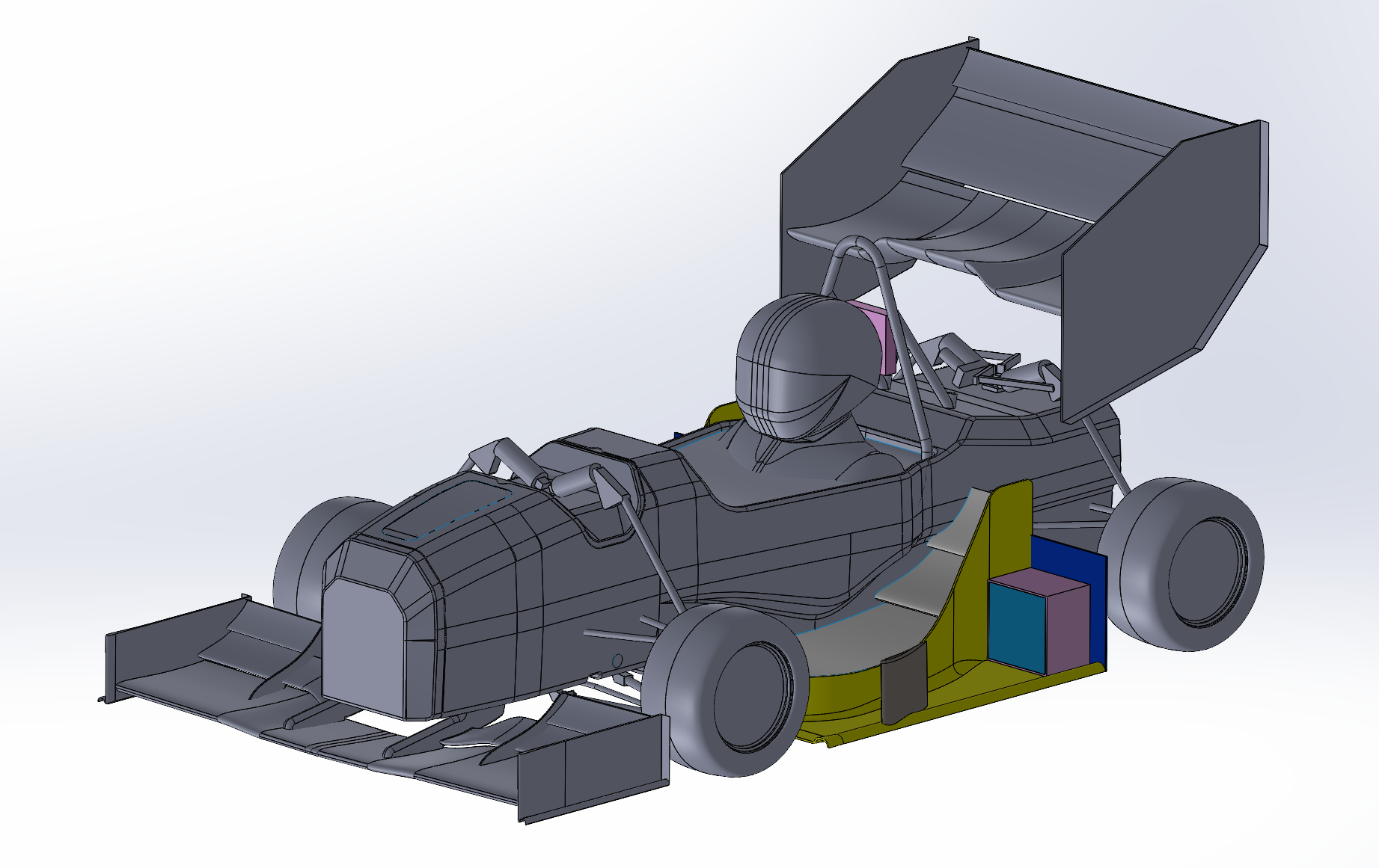
As a second year at Oxford Brookes Racing part of my work in the first semester involved making a new design of the side wings. The main focus was achieving high loading in various operating conditions, while managing flow into the cooling ducts and controlling upwash affecting the rear wing.
Project write-up
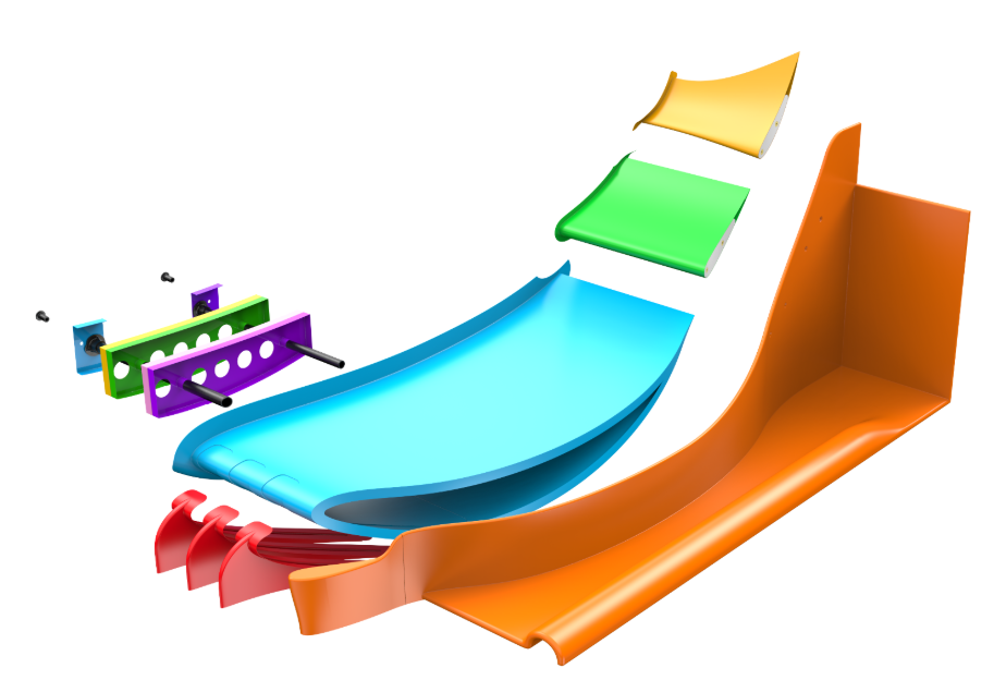
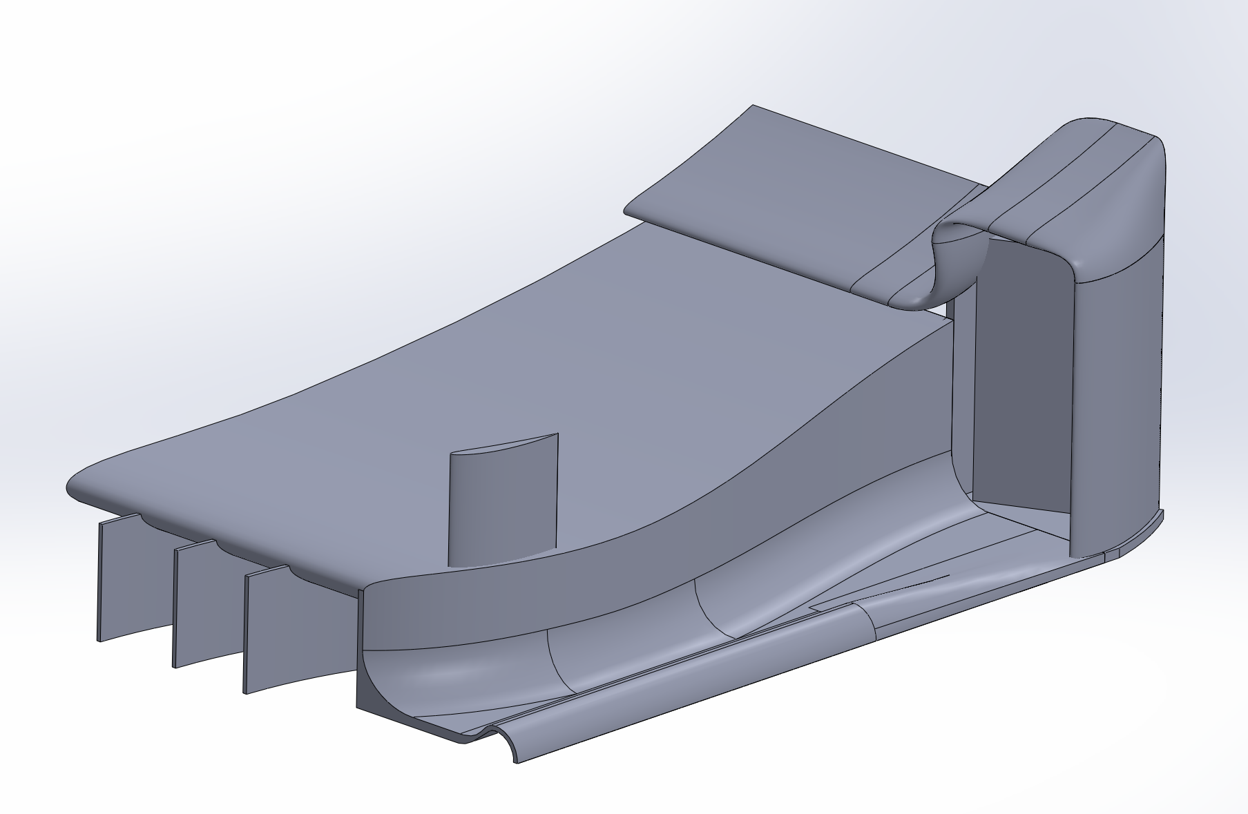
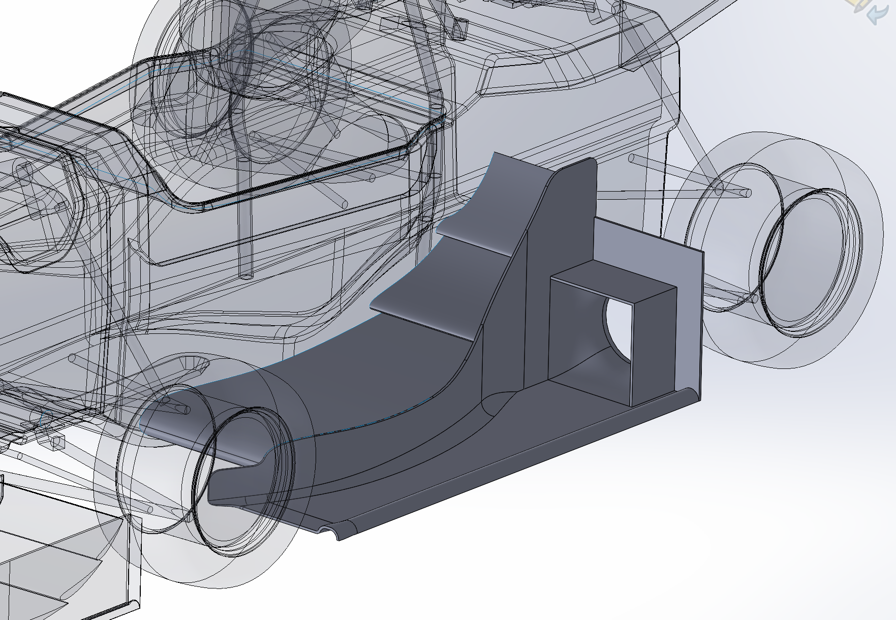
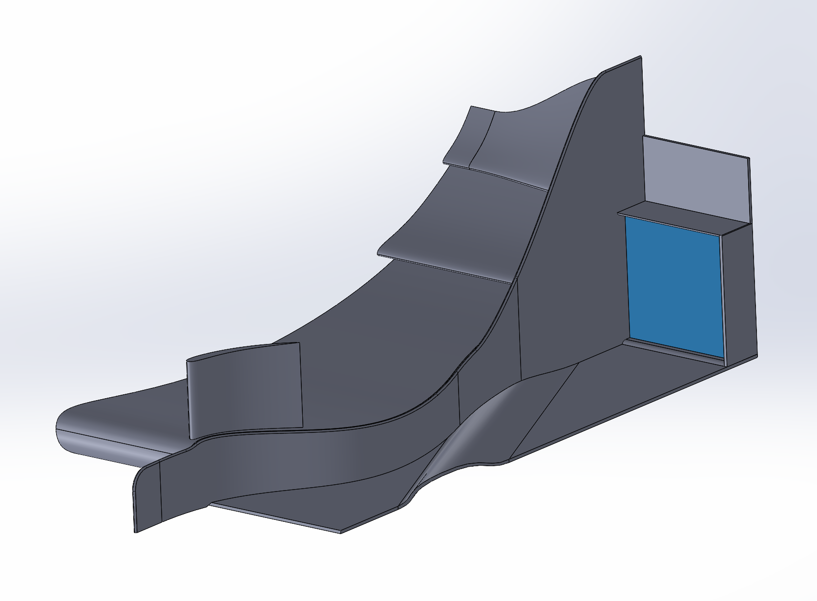
The side wing consists of three main elements: the mainplane and two supporting flaps. The main-element airfoil is fully custom, while the flaps are modified S1223 profiles optimised to work with the mainplane. The mainplane has a chord length of 750 mm and an angle of attack of 4 degrees. The following elements have chord lengths of 190 mm and 170 mm, and angles of attack of 28 and 58 degrees respectively. Flap 2 is tapered inboard, with its inner profile almost two times smaller in chord than the outer profile. This reduces upwash in that section of the flow; keeping the element straight produced an 8 N downforce loss at the rear wing.
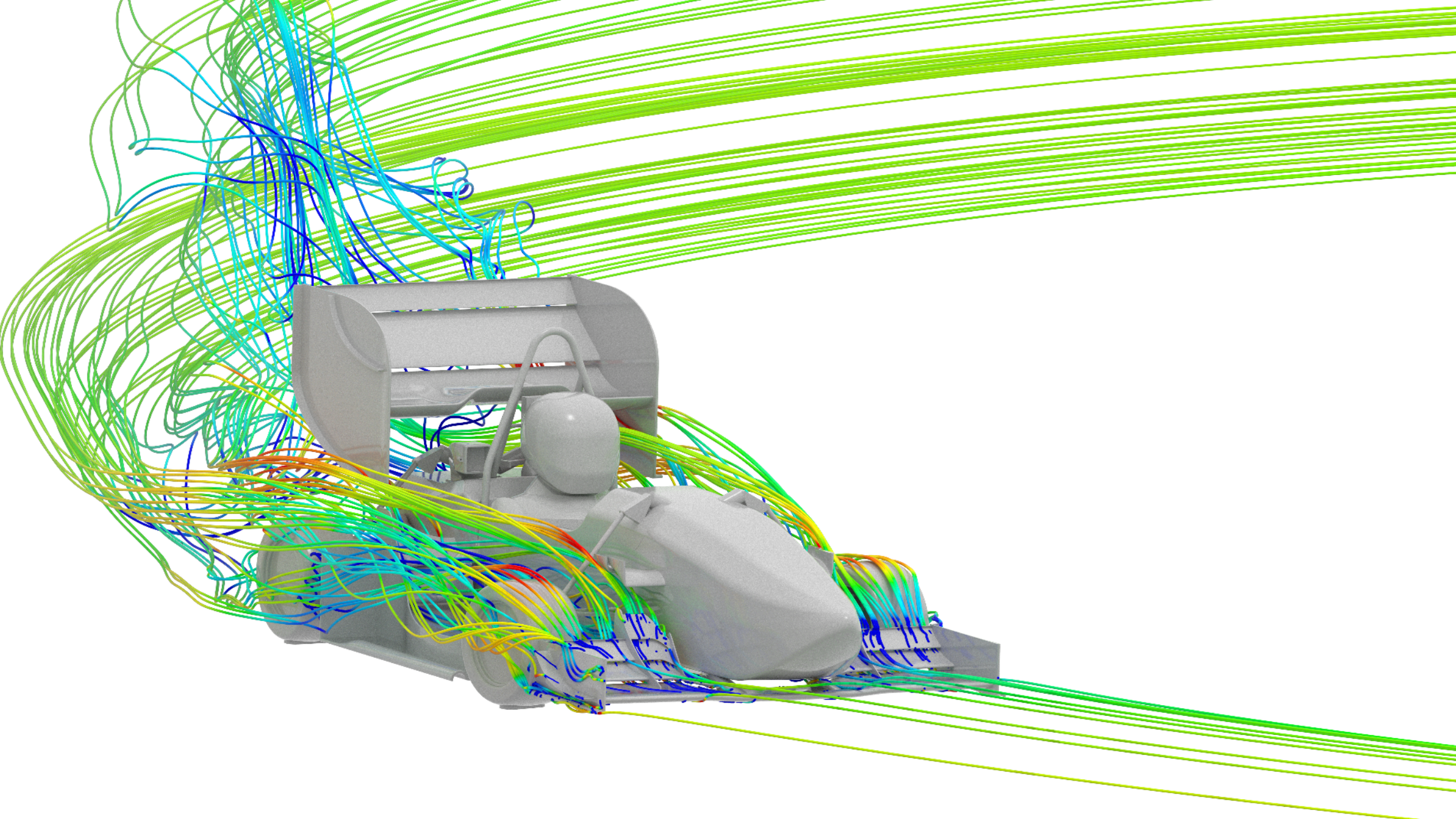
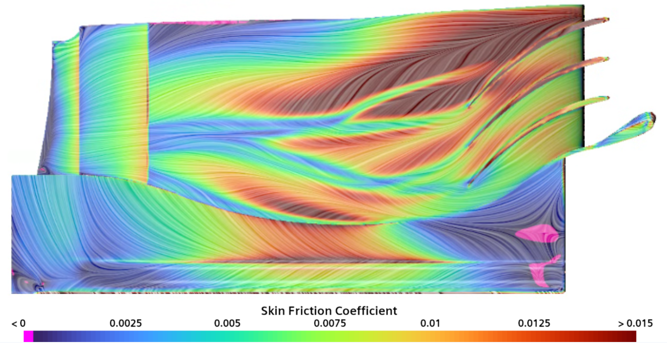
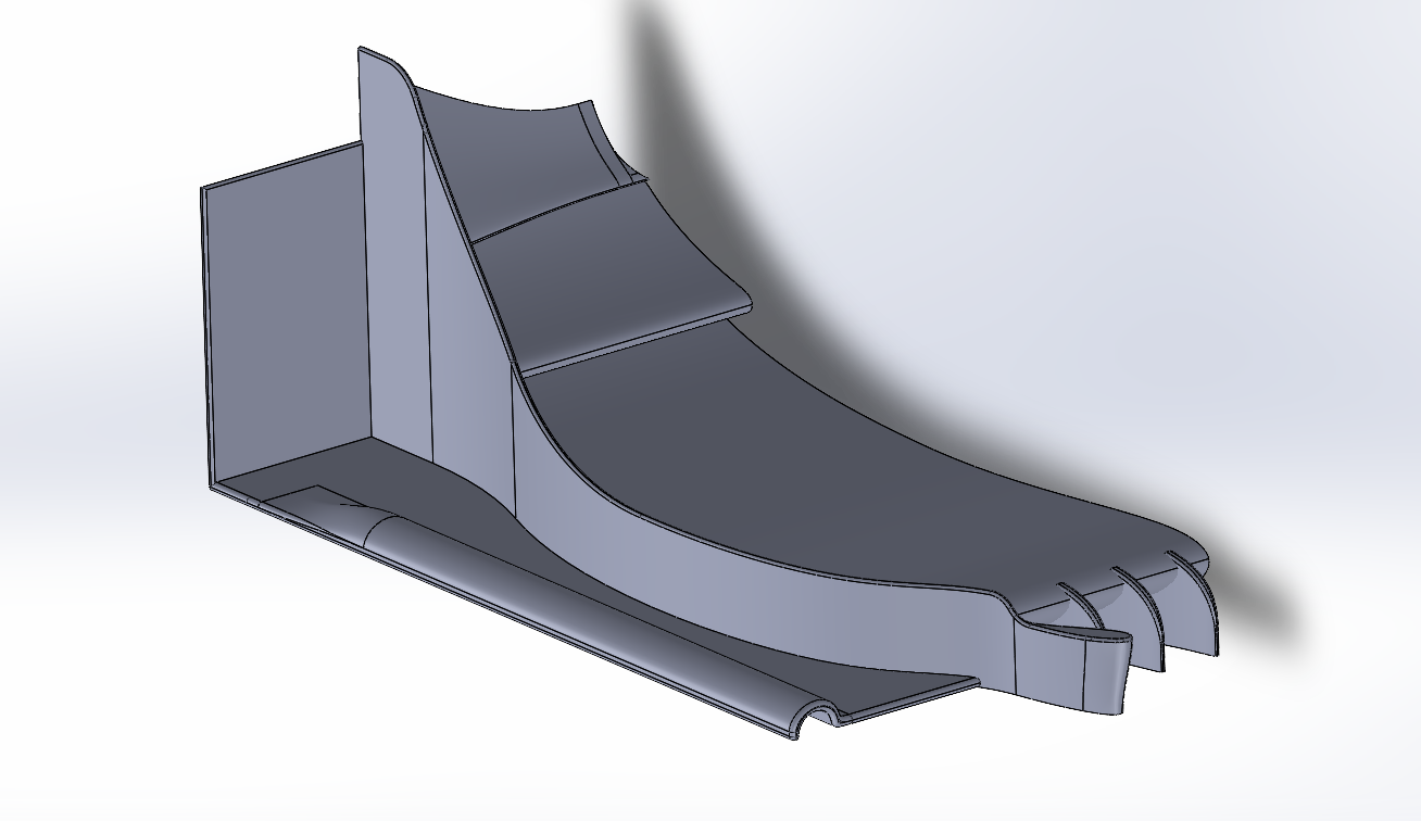
Overall, this combination stays attached throughout the operating conditions, except at very low ride heights or during aggressive pitching and squatting. It achieves a pressure peak of -3.6 and a 0.76 ClA increase compared with the initial OBR25 baseline. The mainplane has three strakes that spool strong vortices with low-pressure cores, improving suction. These vortices merge downstream and help the flow remain attached to the supporting flaps, allowing a high effective angle of attack across the whole wing.
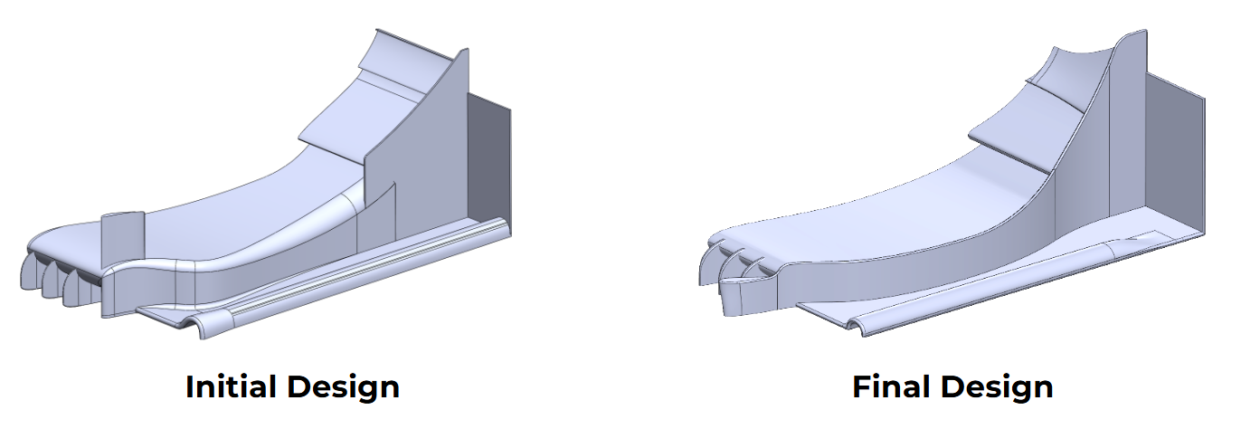
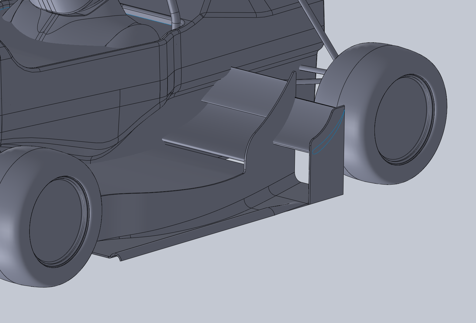
The side-wing side panel is curved to build high pressure behind the tyre and drive low-energy air away from the underfloor. At the front, a turning vane reduces tyre-wake ingress, especially in yaw and crosswind conditions. The lofted geometry was developed through multiple iterations for the largest performance gain.
A C-channel runs through almost the entire length of the elements and maintains a vortex that leaves the outboard edge through a circular tunnel. This vortex limits ambient-air leakage into the underbody and low-pressure flow leakage out of it. At the rear, a vertical wall constrains the rear-tyre stagnation flow and creates outwash.
Design evolution
01 / 06
Images