SR71 Aircraft Model
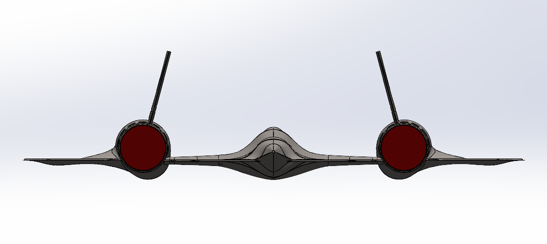
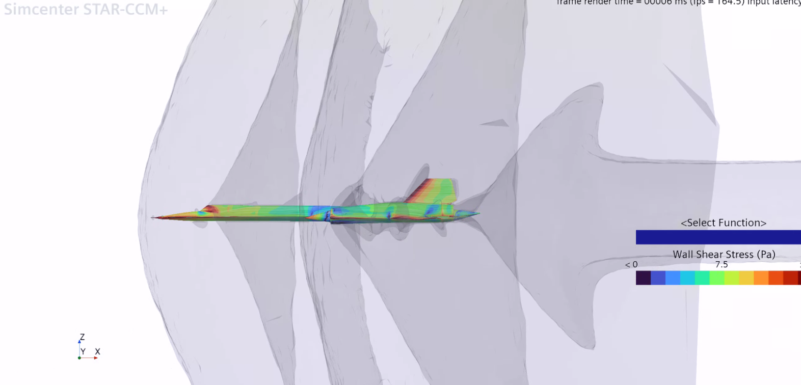
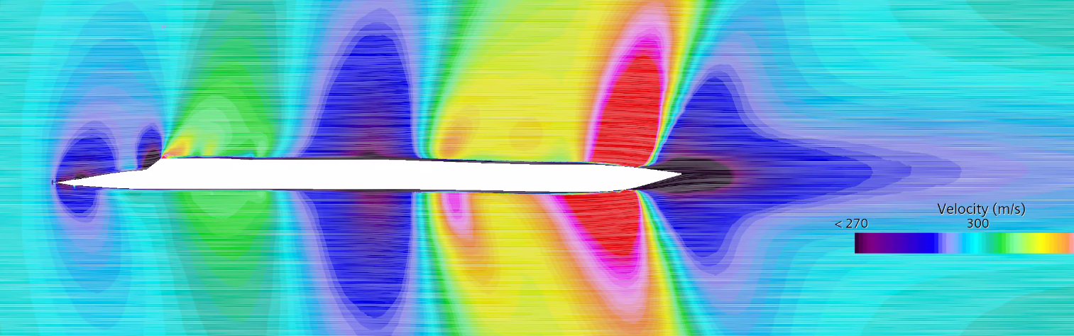
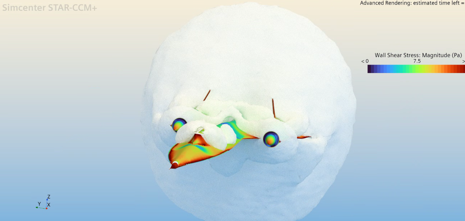
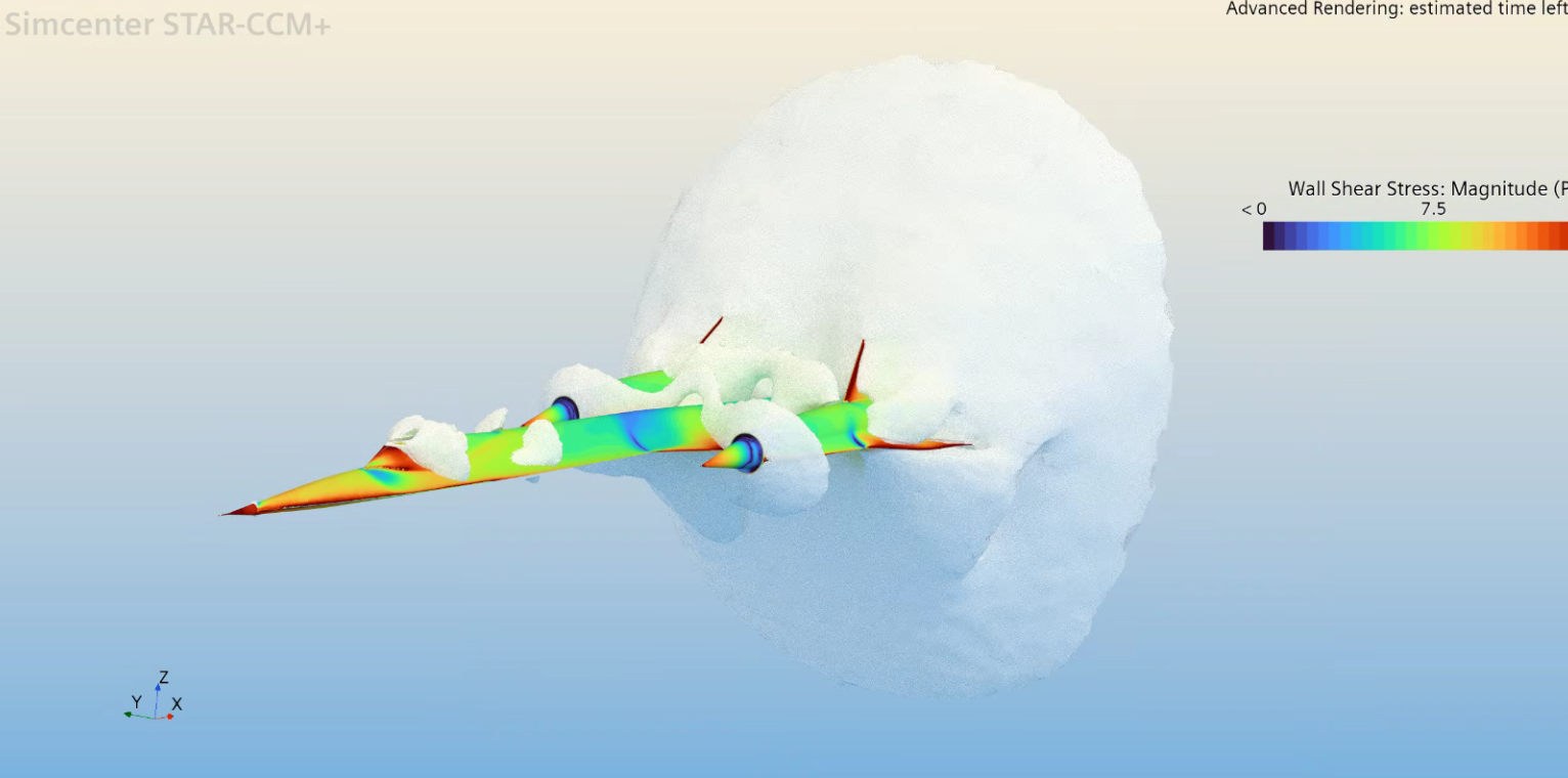
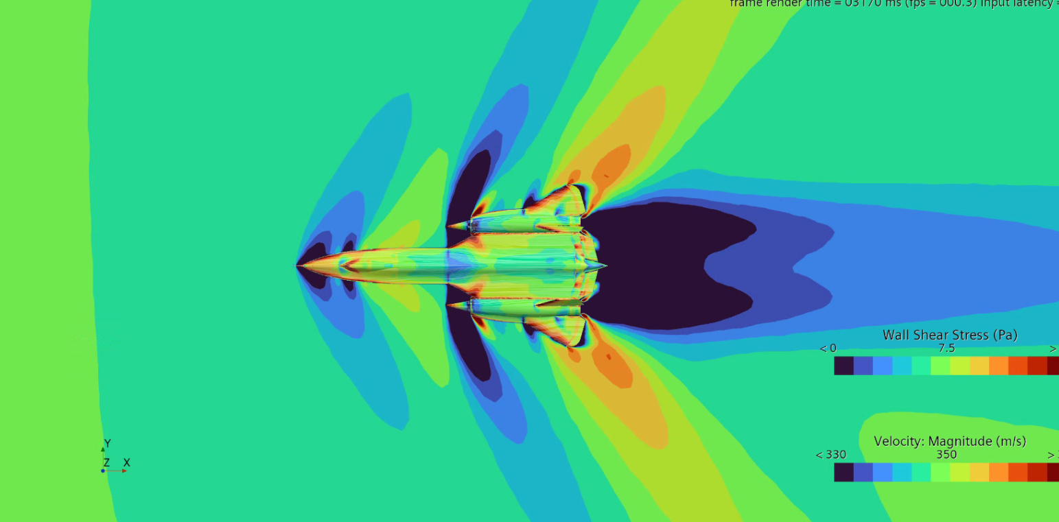
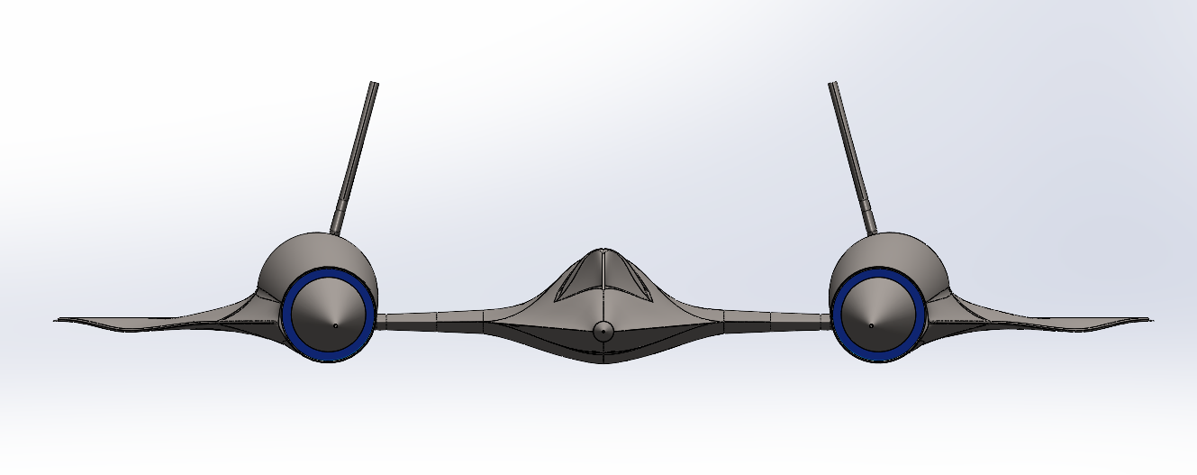
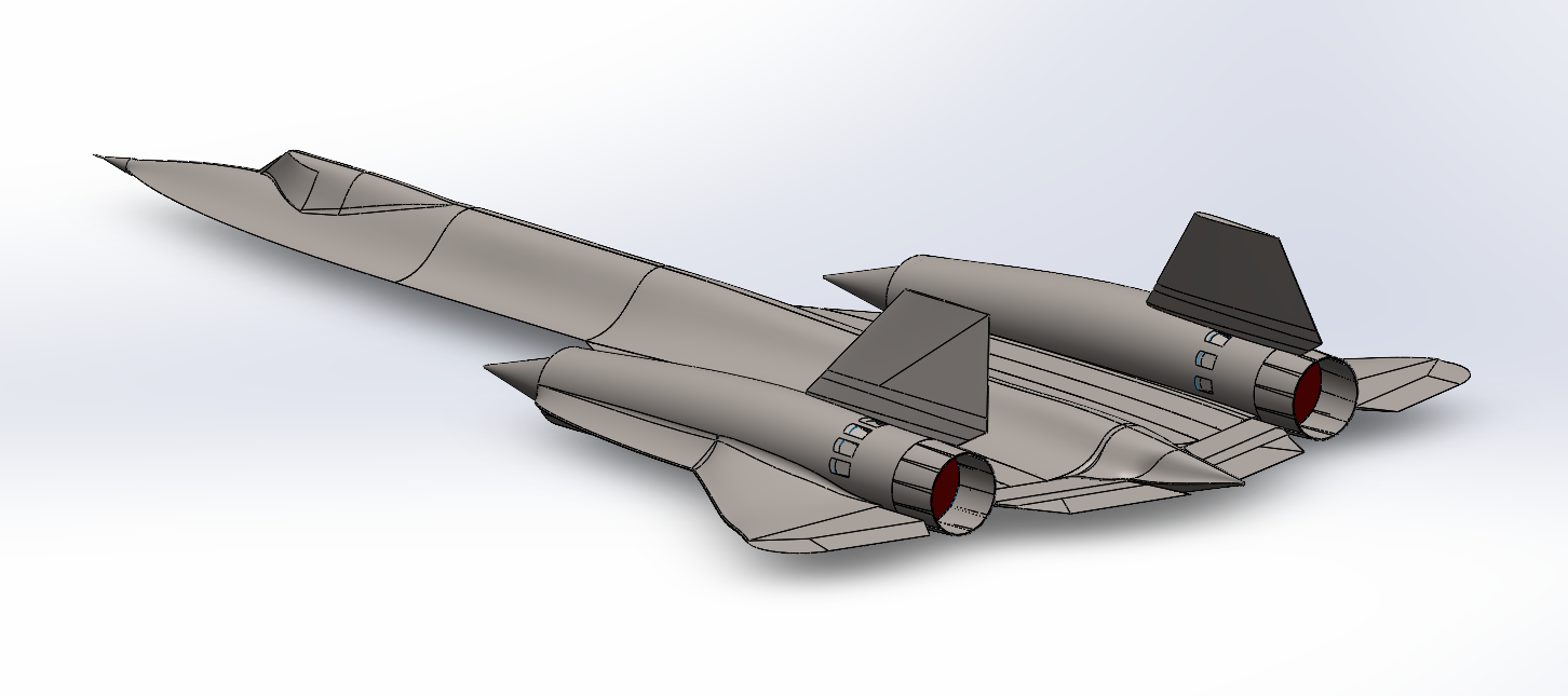
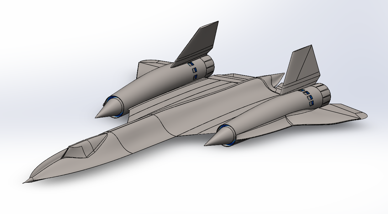
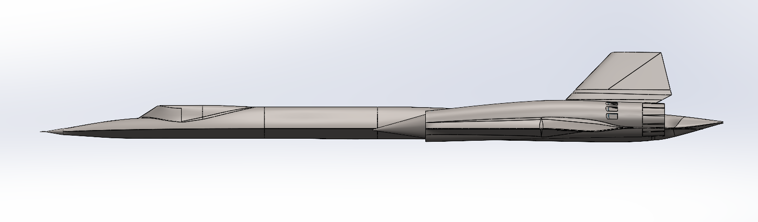
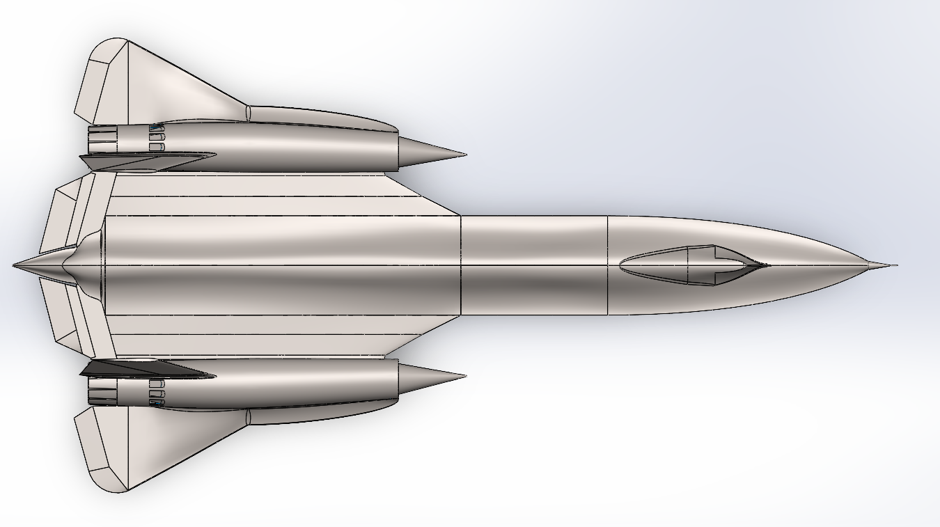
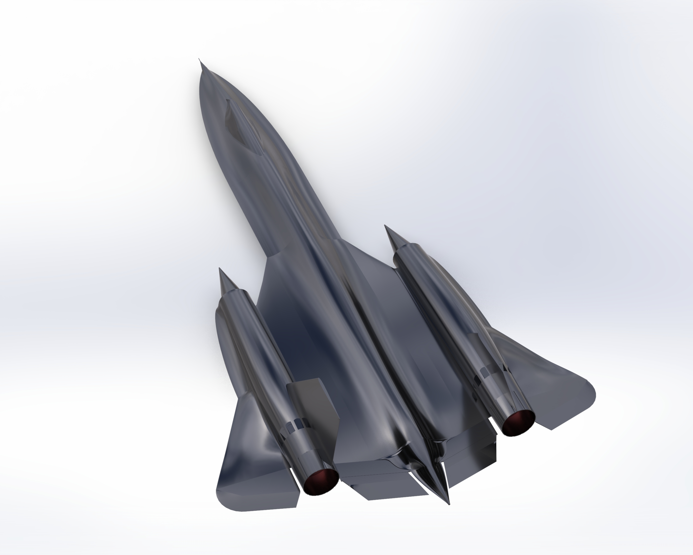
Prepared in SOLIDWORKS, this full scale CAD model of the SR71 blackbird aircraft includes all of its external features and has been optimised for CFD runs.
Project write-up
The SR-71 Blackbird was developed by Lockheed’s Skunk Works during the 1960s as a high-altitude reconnaissance aircraft. It was designed to operate at speeds above Mach 3 and at altitudes of more than 80,000 ft, allowing it to carry out reconnaissance missions while remaining difficult to intercept. Its design was heavily influenced by the aerodynamic and thermal requirements of sustained high-speed flight, which resulted in its distinctive shape, titanium structure and use of Pratt & Whitney J58 engines.
For this project, I decided to recreate the SR-71 in SolidWorks. My goal was not to make a perfectly detailed replica, but to capture the aircraft’s most recognisable shapes and proportions while challenging myself with more complex surface geometry.
The biggest difficulty was definitely the shape of the aircraft itself. The SR-71 does not really have a traditional fuselage with separate wings attached to it. Instead, almost everything flows together. The nose blends into the chines, the chines continue into the wings, and the engine nacelles are integrated into the overall body. Because of this, simple extrudes were not enough for most of the model.
A large part of the fuselage was created using a series of cross-sections positioned along different reference planes. These profiles were then connected using lofted features to gradually build the long, changing shape of the aircraft. Getting these lofts to behave properly was one of the more challenging parts of the project. Small changes in a sketch could create strange curvature, sharp transitions or even cause the feature to fail completely.
The engine nacelles were another interesting part to model. Their main bodies are much more cylindrical than the central fuselage, but they still need to blend smoothly into the wing. I also modelled the characteristic pointed inlet cones at the front and the exhaust sections at the rear. The vertical stabilisers and smaller engine details were comparatively straightforward and could be created using simpler sketches, extrusions and repeated features.
Symmetry helped a lot throughout the process. Since the SR-71 is almost perfectly symmetrical about its centreline, several parts could be modelled on one side and mirrored across the aircraft. This reduced the amount of work while also keeping both sides consistent.
It was a really useful project for learning more about lofts, reference planes, complex geometry and how much planning is required before building an organic shape in CAD. It also gave me a much better appreciation for just how unusual the real SR-71 is from an engineering and aerodynamic point of view.
Some Stats: 25 solid bodies and 28 surface bodies; 52 reference planes; 91 primary 2D sketches and 42 primary 3D sketches; three sketch pictures used as orthographic reference images; 8 surface lofts; 10 boundary surfaces; 30 filled surfaces.
Model
Interactive model
Drag to rotate. Scroll or pinch to zoom.
Images